CLIENT
-
MenuRetour
-
 Smartphones
-
-
 iPhone
-
 Samsung
-
 Xiaomi
-
 Huawei
-
 OnePlus
-
 Sony
Sony
-
 Honor
Honor
-
 LG
LG
-
 Oppo
Oppo
-
 Crosscall
-
 Wiko
Wiko
-
 HTC
HTC
-
Autres Autres
iPhone 11 et supérieur
iPhone X au XS Max
iPhone 6 au 8 Plus
iPhone plus anciens
Apple Watch
iPhone 15 Pro Max iPhone 15 Pro iPhone 15 Plus iPhone 15 iPhone 14 Pro Max iPhone 14 Pro iPhone 14 Plus iPhone 14Galaxy A
Galaxy J
Galaxy M
Galaxy S
Galaxy Z
Galaxy Note
Autres
Montres
Galaxy A90 Galaxy A80 Galaxy A72 Galaxy A71 Galaxy A70 Galaxy A60 Galaxy A55 5G Galaxy A54 Galaxy A53 5G Galaxy A52s 5G Galaxy A52 Galaxy A51 5G Galaxy A51Galaxy A50s Galaxy A50 Galaxy A42 Galaxy A41 Galaxy A40s Galaxy A40 Galaxy A35 5G Galaxy A34 Galaxy A33 5G Galaxy A33 Galaxy A32 5G Galaxy A32 Galaxy A31Galaxy A30s Galaxy A30 Galaxy A25 5G Galaxy A24 4G Galaxy A23 5G Galaxy A23 Galaxy A22 5G Galaxy A22 Galaxy A21s Galaxy A21Galaxy A20s Galaxy A20e Galaxy A20 Galaxy A15 Galaxy A14 5G Galaxy A14 Galaxy A13 5G Galaxy A13 Galaxy A12 Galaxy A11Galaxy J8 Galaxy J7+ Galaxy J7 Pro Galaxy J7 Prime Galaxy J7 Max Galaxy J7 Core Galaxy J7 (2018) Galaxy J7 (2017) Galaxy J7 (2016) Galaxy J7 Galaxy J6+ Galaxy J6 (2018)Galaxy S24 Ultra Galaxy S24+ Galaxy S24 Galaxy S23 FE Galaxy S23 Ultra Galaxy S23+ Galaxy S23 Galaxy S22 Ultra Galaxy S22+ Galaxy S22Galaxy S21 FE Galaxy S21+ Galaxy S21 Ultra Galaxy S21 Galaxy S20 FE 5G Galaxy S20+ Galaxy S20 Ultra Galaxy S20 FE Galaxy S20Galaxy S10e Galaxy S10+ Galaxy S10 Lite Galaxy S10 5G Galaxy S10 Galaxy S9+ Galaxy S9 Galaxy S8+ Galaxy S8 Active Galaxy S8Galaxy Ace 1 Galaxy Ace 2 Galaxy Ace 3 Galaxy Ace 4 Galaxy Ace 4 Lite Galaxy Ace Duos Galaxy Ace Style Galaxy AlphaGalaxy C5 Galaxy C5 Pro Galaxy C5000 Galaxy C7 Galaxy C7 Prime Galaxy C7 Pro Galaxy C8 Galaxy C9 Galaxy C9 Pro Galaxy Core 2 Galaxy Core LTE Galaxy Core Prime Galaxy Core Prime VEGalaxy Gio S5660 Galaxy Grand 2 Galaxy Grand Max Galaxy Grand Neo Galaxy Grand Plus Galaxy Grand Prime Galaxy Grand Prime +Série 11 et plus
Série Mi
Série Mi Note
Série Mi Max/Mi Mix
Série Redmi
Série Redmi Note
Série Pocophone
Xiaomi Mi 11 Pro Xiaomi Mi 11 Lite 5G Xiaomi Mi 11 Ultra Xiaomi Mi 11 Lite Xiaomi Mi 11i Xiaomi Mi 11 Xiaomi Mi 10T Pro Xiaomi Mi 10T Lite Xiaomi Mi 10T Xiaomi Mi 10 Pro Xiaomi Mi 10 Lite Xiaomi Mi 10Xiaomi Mi 9T Pro Xiaomi Mi 9T Xiaomi Mi 9 SE Xiaomi Mi 9 Lite Xiaomi Mi 9 Xiaomi Mi8 SE Xiaomi Mi 8 Pro Xiaomi Mi 8 Lite Xiaomi Mi 8 Xiaomi Mi 6Xiaomi Redmi 13C Xiaomi Redmi 12C Xiaomi Redmi 12 4G/5G Xiaomi Redmi 10 (2022) Xiaomi Redmi 10C Xiaomi Redmi 10A Xiaomi Redmi 10 Xiaomi Redmi 9AT Xiaomi Redmi 9T Xiaomi Redmi 9C Xiaomi Redmi 9A Xiaomi Redmi 9Xiaomi Redmi 8A Xiaomi Redmi 8 Xiaomi Redmi 7A Xiaomi Redmi 7 Xiaomi Redmi 6A Xiaomi Redmi 6 Xiaomi Redmi 5A Xiaomi Redmi 5 Plus Xiaomi Redmi 5Xiaomi Redmi Note 13 Pro+ 5G Xiaomi Redmi Note 13 Pro 5G Xiaomi Redmi Note 13 Pro 4G Xiaomi Redmi Note 13 5G Xiaomi Redmi Note 13 4G Xiaomi Redmi Note 12S Xiaomi Redmi Note 12 Pro+ Xiaomi Redmi Note 12 Pro 5G Xiaomi Redmi Note 12 Pro 4G Xiaomi Redmi Note 12 5G Xiaomi Redmi Note 12 4G Xiaomi Redmi Note 11 Pro+ 5G Xiaomi Redmi Note 11 Pro 4G/5GSérie Mate
Série P
Série P Smart
Série Ascend
Autres
One plus
Série Z
Série X
Autres
Honor
Honor Magic
Honor View
Série G
Série Optimus
Autres
Optimus 2X (Speed) LG Optimus 3D LG Optimus 3D Max LG Optimus 4X HD LG Optimus Black LG Optimus G LG Optimus G Pro LG Optimus G2Série A
Série Find
Série Reno
Autres
Crosscall
Série View
Série Y
Série Cink
Série Sunny
Série Lenny
Série U
Autres
Wiko Barry Wiko Birdy Wiko Bloom Wiko Darkfull Wiko Darkmoon Wiko Darknight Wiko Darkside Wiko Fever 4G Wiko Fever SE Wiko Fizz Wiko FreddyWiko Getaway Wiko GOA Wiko Harry Wiko Harry 2 Wiko Highway 4G Wiko Highway Pure Wiko Highway Signs Wiko Highway Star Wiko IggyWiko Jerry Wiko Jerry 2 Wiko Jerry 3 Wiko Jerry Max Wiko Jimmy Wiko Kenny 4G Wiko Kite Wiko Ozzy Wiko Pulp 4G Wiko Pulp Fab 4GHTC Desire
HTC One
Autres
HTC Desire 820 HTC Desire 816 HTC Desire 626G Dual SIM HTC Desire 626 HTC Desire 620G Dual SIM HTC Desire 620 HTC Desire 610 HTC Desire 601 HTC Desire 600Alcatel
Asus
BlackBerry
Realme
Google
Meizu
Microsoft Lumia
Motorola
Nokia
Zenfone 9 Zenfone 6 Zenfone 5 Zenfone 4 Selfie Pro Zenfone 4 Zenfone 3 Ultra Zenfone 3 Max Zenfone 3 Deluxe Zenfone 3 Zenfone 2 Laser Zenfone 2 -
-
-
 Tablettes
-
-
iPad
-
 Samsung
-
 Microsoft
-
Autres Autres
iPad
iPad Air
iPad Mini
iPad Pro
Galaxy Tab
Galaxy Tab S
Galaxy Note
Autres
Surface Pro
Autres
ASUS
ACER
SONY
LG
Nexus
-
-
-
 Consoles de jeux
-
-
 Nintendo
-
 Sony
Sony
-
 Microsoft
Nintendo Switch
Nintendo DS
Autres
Playstation
PSP
Autres
Xbox Série
Xbox One
Xbox 360
-
-
-
 Mac
Mac
-
-
 MacBook Air
-
 MacBook Pro
-
 MacBook
-
Autres Autres
-
 iMac
iMac
MacBook Air 11"
MacBook Air 13"
MacBook Air 13 pouces 2022 M2 (A2681 - EMC 4074) MacBook Air 13 pouces - A2337 MacBook Air 13" 2020 (A2179 - EMC 3302) MacBook Air 13" 2019 (A1932 - EMC 3184) Macbook Air 13" Début 2018 (A1932 - EMC 3184) MacBook Air 13"" Début 2017 (A1466 - EMC 3178) MacBook Air 13" Début 2015 (A1466 - EMC 2925) MacBook Air 13" Début 2014 (A1466 - EMC 2632)MacBook Air 13" Mi 2013 (A1466 - EMC 2632) MacBook Air 13" Mi 2012 (A1466 - EMC 2559) MacBook Air 13" Mi 2011 (A1369 - EMC 2469) MacBook Air 13" Fin 2010 (A1369 - EMC 2392) MacBook Air 13" Mi 2009 (A1304 - EMC 2334) MacBook Air 13" Fin 2008 (A1304 - EMC 2253) MacBook Air 13" Début 2008 (A1237 - EMC 2142)MacBook Pro 13"
MacBook Pro 14"
MacBook Pro 15"
MacBook Pro 16"
MacBook Pro 17"
MacBook Pro Retina 13" 2020 (A2338) MacBook Pro 13" A2289 MacBook Pro 13" 2020 (A2251 A2159 - EMC 3348) Macbook Pro 13" Retina Début 2019 (A1989 A2159) MacBook Pro 13" Mi 2018 (A1989 EMC 3214) MacBook Pro 13" Retina Mi 2017 (A1708 A1706) MacBook Pro 13" Retina Fin 2016 (A1708 A1706) MacBook Pro 13" Retina Début 2015 (A1502 - EMC 2835) MacBook Pro 13" Retina Mi 2014 (A1502 - EMC 2875) MacBook Pro 13" Retina Fin 2013 (A1502 - EMC 2678) MacBook Pro 13" Retina Début 2013 (A1425 - EMC 2672)MacBook Pro 13" Retina Fin 2012 (A1425 - EMC 2557) MacBook Pro 13" Unibody Mi 2012 (A1278 - EMC 2554) MacBook Pro 13" Unibody Fin 2011 (A1278 - EMC 2555) MacBook Pro 13" Unibody Début 2011 (A1278 - EMC 2419) MacBook Pro 13" Unibody Mi 2010 (A1278 - EMC 2351) MacBook Pro 13" Unibody Mi 2009 (A1278 - EMC 2326) MacBook Pro 13" Unibody Fin 2008 (A1278 - EMC 2254)MacBook Pro 15" Retina Mi 2019 (A1990 - EMC 3359) MacBook Pro 15" Retina Mi 2018 (A1990 - EMC 3215) MacBook Pro 15" Retina Mi 2017 (A1707 - EMC 3162) MacBook Pro 15" Retina Fin 2016 (A1707 - EMC 3072) MacBook Pro 15" Retina Mi 2015 (A1398 - EMC 2909/2910) MacBook Pro 15" Retina Mi 2014 (A1398 - EMC 2876 & 2881) MacBook Pro 15" Retina fin 2013 (A1398 - EMC 2674 & 2745) MacBook Pro 15" Retina Début 2013 (A1398 - EMC 2673) MacBook Pro 15" Retina Mi 2012 (A1398 - EMC 2512) MacBook Pro 15" Unibody Mi 2012 (A1286 - EMC 2556)MacBook Pro 15" Unibody Fin 2011 (A1286 - EMC 2563) MacBook Pro 15" Unibody Début 2011 (A1286 - EMC 2353-1) MacBook Pro 15" Unibody Mi 2010 (A1286 - EMC 2353) MacBook Pro 15" Unibody Mi 2009 (A1286 - EMC 2324 & 2325) MacBook Pro 15" Unibody Début 2009 (A1286 - EMC 2255) MacBook Pro 15" Unibody Fin 2008 (A1286 - EMC 2255) MacBook Pro 15" Début 2008 (A1260 - EMC 2198) MacBook Pro 15" Mi/Fin 2007 (A1226 - EMC 2136) MacBook Pro 15" Fin 2006 (A1211 - EMC 2120) MacBook Pro 15" Original 2006 (A1150 - EMC 2101)MacBook 12"
MacBook 13"
iBook
Mac Mini
Mac Pro
PowerBook
Mac Mini Fin 2014 (A1347 - EMC 2840) Mac Mini Fin 2012 (A1347 - EMC 2570) Mac Mini Mi 2011 (A1347 - EMC 2442) Mac Mini Mi 2010 (A1347 - EMC 2364)iMac 20"
iMac 21.5"
iMac 24"
iMac 27"
iMac G5
-
-
-
 Electro & transport
-
-
 Dyson
Dyson
-
 Kärcher
-
 Trottinettes
Série DC
Série V
Autres
DC15 Allergy DC19 Allergy DC19 Base DC19 Exclusive DC19 T2 Origin DC20 Allergy DC20 AnimalPro DC21 Motorhead DC22 AnimalPro DC22 Exclusive DC23 Origin DC23 T2 Origin DC24 Multi FloorDC25 Allergy DC26 Allergy Parquet DC26 City Vac DC29 Allergy DC29 Allergy Complete DC29 Allergy Parquet Plus DC29 Allergy Parquet Plus DC29 AnimalPro DC29 DB Allergy Parquet DC29 AnimalPro DC29 DB Multi Floor DC30 DC31DC31 AnimalPro DC31 Car and Boat DC32 DC32 Allergy Parquet DC32 AnimalPro DC33C Allergy DC33C Allergy Musclehead DC33C Allergy Parquet DC33C Origin DC33C Origin Plus DC33C Triggerhead DC34 DC35 Dyson Digital SlimAspirateurs Série A
Aspirateurs Série WD
Aspirateurs Autres
Nettoyeurs vitres
Nettoyeurs vapeur
Kärcher WD 7300 Kärcher WD2200 Kärcher WD2250 Kärcher WD3 PREMIUM Kärcher WD3200 Kärcher WD3300 Kärcher WD3300M Kärcher WD3500 Kärcher WD3500P Kärcher WD4Kärcher 2001 Kärcher 2101 Kärcher 2111 Kärcher 2201 Kärcher 2201F Kärcher 2251 Kärcher 2301 Kärcher 2501 Kärcher 2601 Kärcher 3000PLUS Kärcher 3001 Kärcher 3011 Kärcher 3501Kärcher 4000Plus Kärcher DS5800 Kärcher FC5 Kärcher K1000 Kärcher K2201 Kärcher KB6060C Kärcher MV2 Kärcher MV3 Kärcher MV3 PREMIUM Kärcher MV4 Kärcher MV4 PREMIUM Kärcher MV5 Kärcher MV5PREMIUMKärcher SC1 EASY FIX Kärcher SC1000 Kärcher SC1002 Kärcher SC1010 Kärcher SC1020 Kärcher SC1030 Kärcher SC1030B Kärcher SC1035B Kärcher SC1040 Kärcher SC1050 Kärcher SC1052 Kärcher SC1402 Kärcher SC1475Kärcher SC1502 Kärcher SC1502I Kärcher SC1650 Kärcher SC1650BE Kärcher SC1702 Kärcher SC1702I Kärcher SC1702I6002 Kärcher SC2 Kärcher SC2 EASY FIX Kärcher SC2000 Kärcher SC2500C Kärcher SC2500C127V Kärcher SC2500C220Kärcher SC2550 Kärcher SC2550C Kärcher SC2600C Kärcher SC2600CB Kärcher SC3 Kärcher SC3 Premium Kärcher SC3000 Kärcher SC3100 Kärcher SC3100B Kärcher SC4 Kärcher SC4100 Kärcher SC4100C Kärcher SC4100CBTrottinettes
-
-
-
 Accessoires
-
-
 Accessoires
-
-
-
 Outils
-
-
 Outils
-
-
 Guides
 Identification modèle
 Support / Assistance
 Charge
 Audio
Audio
 Coques / Housses
 Verres trempés
 Films hydrogel
 Supports smartphone, AirTag, Tours de cou
 Accessoires Apple Watch
 Accessoires Mac
 Accessoires consoles
 Accessoires télétravail
 Ouverture et déconnexion
 Pinces et ventouses
 Couper
 Kits outils
 Inspection
 Soudure et câblage
 Mesure
 Organisation
 Décharge
 Consommables
 Nettoyage
 Tournevis et clés
 Outils gTool
 Professionnels
 Hygiène
 Découpe de film
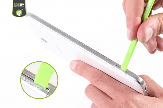
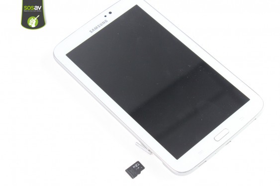
Guide de réparation : Carte MicroSD Galaxy Tab 3 7"
Si vous manquez de place pour vos photos et vidéos, que vous rencontrez des problèmes pour lire et écrire sur la carte MicroSD de votre Galaxy Tab 3 7", vous pouvez heureusement remedier à ce souci par son remplacement en suivant les conseils des experts de SOSav qui vous ont concocté ce guide de réparation illustré et commenté !
Symptômes :
- Tiroir MicroSD cassé
- Carte MicroSD non lisible

Comment remplacer carte microsd pour Galaxy Tab 3 7" - Guide images
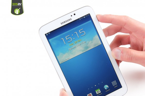
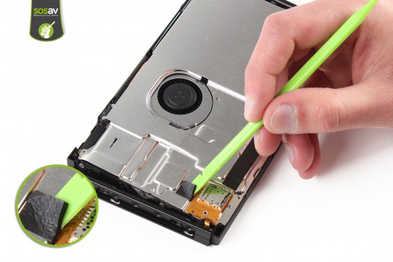
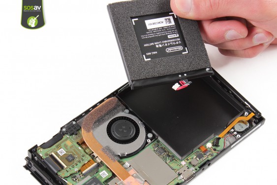
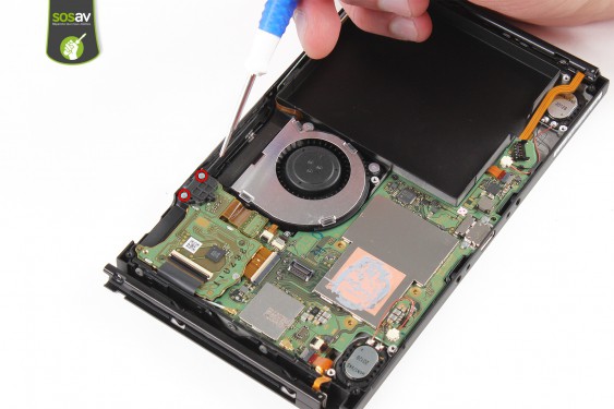
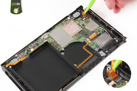
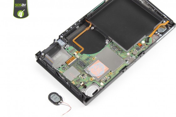
Etape 1
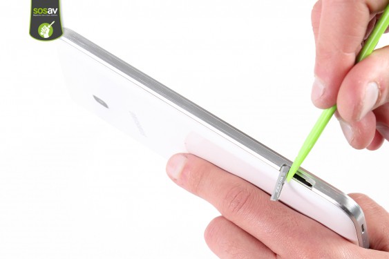
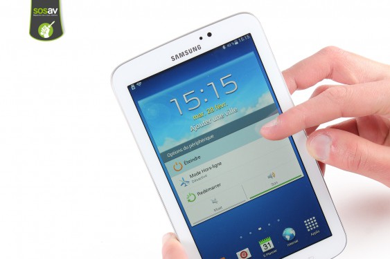
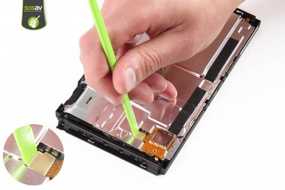
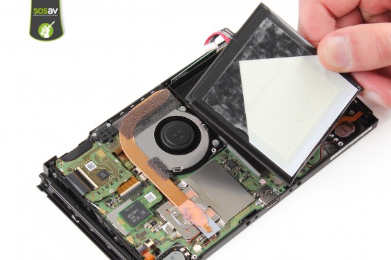
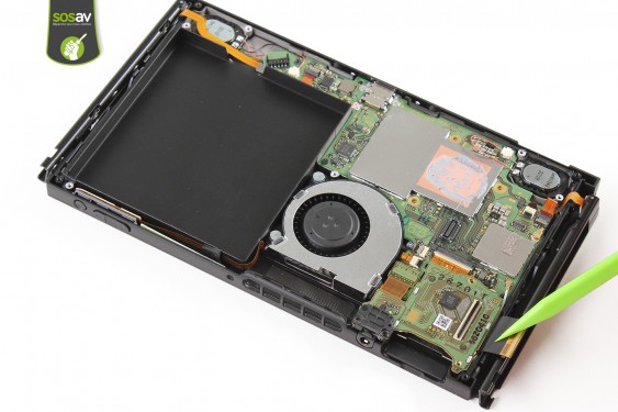
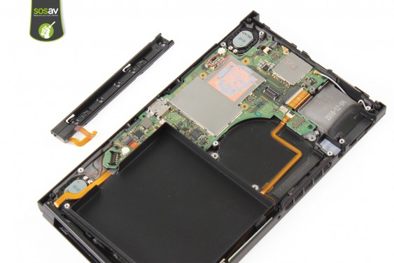
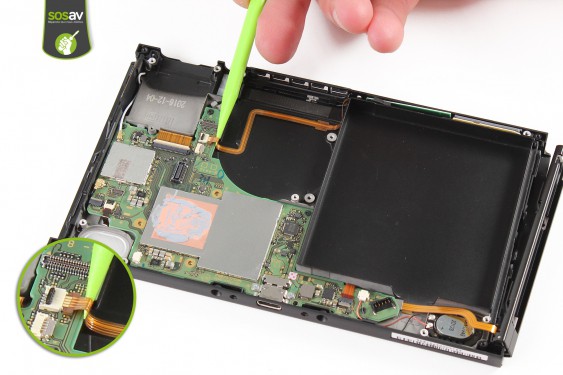
Etape 2
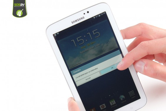
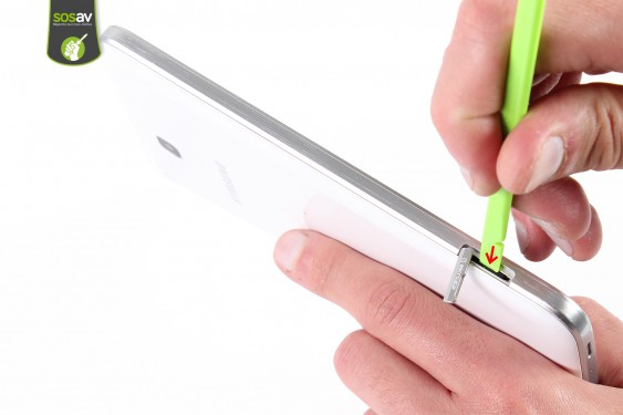
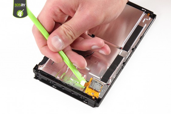
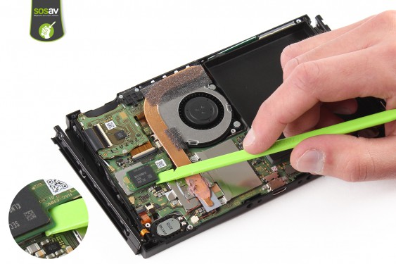
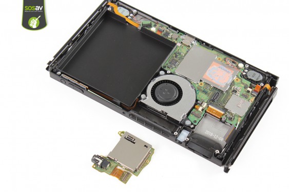
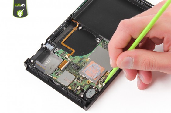
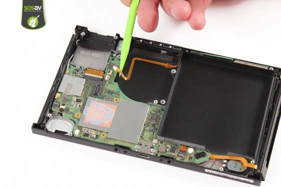
Etape 3
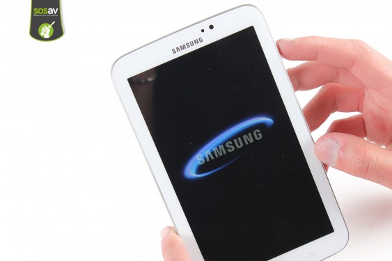
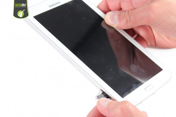
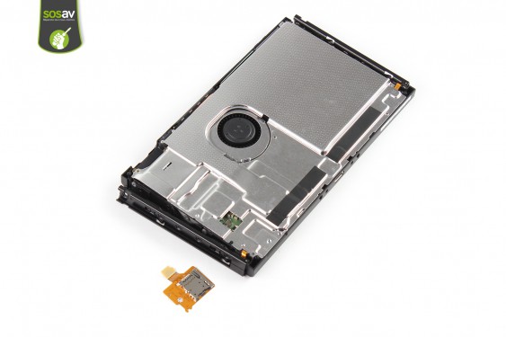
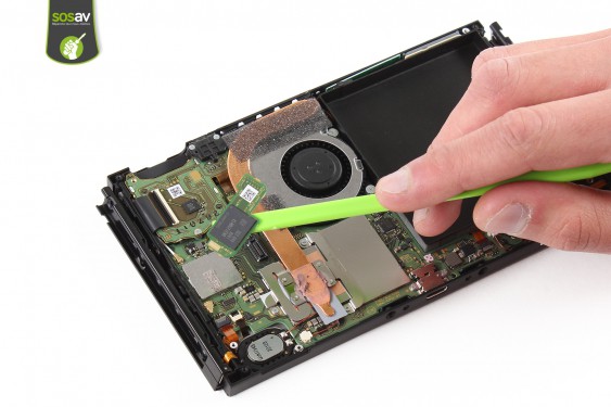
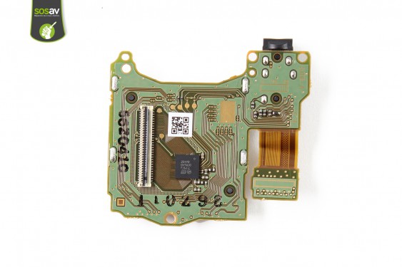
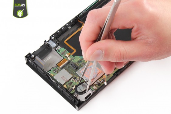
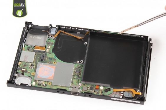
Etape 4
Etape 5
Etape 6
Etape 7
Etape 8
Etape 9
Etape 10
Etape 11
Etape 12
Etape 13
Etape 14
Etape 15
Etape 16
Etape 17
Etape 18
Negative side :- The use of many screws like the « Tri-wing » can discourage the repair : one screw type (cruciform) would have been preferable. Too bad ! - The dock connector replacement can?t be without a weld.